Audio/Power Isolation
Full Schematics for Full Audio/Power Isolation by Kle7rx (This design has not been real-world tested yet)
Complete wiring diagrams with parts lists are available as PDFs:
- PCM5102 Build Schematic: I2S DAC + LTK5128 amplifiers
- VS1053 Build Schematic: VS1053 decoder + LTK5128 amplifiers
Both builds share a common power architecture: a MORNSUN F0505S-3WR2 isolated DC-DC converter separates the digital side (ESP32, DAC, display) from the analog/amplifier side, eliminating ground-loop noise. Each functional block (POWER, AUDIO, DIGITAL, DISPLAY) uses a PLY17BN9612R0B2B common-mode choke for additional noise filtering.
Common Parts (Both Builds)
| Part | Qty | Purpose | Alternatives |
|---|---|---|---|
| ESP32-S3-DevKitC-1 N16R8 | 1 | Main microcontroller with 16MB flash and 8MB PSRAM | Any ESP32-S3 with minimum 8MB flash and 2MB PSRAM |
| RS-15-5 (MEAN WELL) | 1 | 5V 15W AC-DC power supply | USB-C PD trigger board (5V), any regulated 5V 3A+ supply |
| F0505S-3WR2 (MORNSUN) | 1 | Isolated 5V→5V DC-DC (3W, 600mA); ultra-low 20pF isolation capacitance for clean analog/digital separation | Requires ≥3W for ESP32-S3; cheaper converters lack both power and low isolation capacitance |
| PLY17BN9612R0B2B (discontinued) | 5 | Murata hybrid CM+DM choke (0.96mH CM, 47μH DM); filters common-mode and differential noise | Würth 7446122001 (1mH, 2A, best direct replacement); KEMET SC-02-10GS (1mH, 2A, toroidal); standard CM choke ≥2A, 0.5–2mH |
| LTK5128 | 2 | Class AB 3W audio amplifier (Left + Right) | PAM8406 (Class D, 5W), PAM8403 (3W), MAX98357A (I2S, 3W) |
| LD06AJSA | 1 | LED constant-current driver; supports LED filaments for encoder illumination | 220Ω resistor + LED (simpler), any 20mA LED driver |
| RCH664NP-100M | 1 | 100μH shielded power inductor for DC-DC filtering | Any 100μH 1A+ shielded inductor; toroidal core inductor (100μH, 1A+) |
| EI14 600:600Ω | 1 | 1:1 audio isolation transformer (line-level) | Any 600:600Ω audio transformer, 10μF DC blocking caps |
| EC11 | 1 | Rotary encoder (15 pulse/30 detent) with push switch | KY-040, PEC11, any quadrature encoder with switch |
| VS1838B | 1 | 38kHz IR receiver | TSOP38238, TSOP4838, TSOP31238 |
| SD Card module | 1 | SPI microSD card reader for offline playback | Built-in display SD slot (check for proper resistors!) |
| XRR6H-6*10-3T | 7 | 6-hole ferrite bead (6×10mm, 3-turn); EMI suppression on signal/power lines | Any 6-hole ferrite bead (6×10mm), clip-on ferrite choke, toroidal ferrite core |
Capacitors & Resistors
| Component | PCM5102 | VS1053 | Where Used | Notes |
|---|---|---|---|---|
| 2200 μF 25V electrolytic | 1 | 1 | Audio rail bulk decoupling | Must use Low ESR |
| 1000 μF 16V electrolytic | 2 | 2 | Amp L+R power, PSU input | Must use Low ESR |
| 470 μF 16V electrolytic | 3 | 3 | Digital rail, Display, LED power | Should use Low ESR |
| 100 μF 16V electrolytic | 2 | 2 | LED driver, SD card | |
| 47 μF 10V electrolytic | 2 | 2 | Digital rail, IR receiver | |
| 10 μF 10V electrolytic | 1 | 1 | DC-DC output filtering | |
| 4.7 μF 10V electrolytic | 1 | 1 | DC-DC output filtering | |
| 0.1 μF ceramic (MLCC) | ~12 | ~12 | Decoupling on all ICs and rails | X7R dielectric |
| 33 Ω resistor (1/4W) | 6 | 6 | SPI bus damping resistors | On MOSI, SCLK, MISO, CS, DC lines |
| 100 Ω resistor (1/4W) | 2 | 5 | IR receiver, VS1053 control lines |
Kle7rx recommends using Low ESR for all electrolytic capacitors. It is also recommended to use metal film resistors but carbon film resistors are acceptable.
PCM5102 Build: Additional Parts
| Part | Qty | Purpose | Alternatives |
|---|---|---|---|
| GY-PCM5102 | 1 | I2S DAC module (PCM5102A chip) | PCM5102A breakout, MAX98357A (amp+DAC combo) |
VS1053 Build: Additional Parts
| Part | Qty | Purpose | Alternatives |
|---|---|---|---|
| VS1053B module | 1 | SPI MP3/AAC/FLAC/OGG decoder + DAC | VS1003 (MP3 only), WM8960 (I2S codec) |
| 10 kΩ resistor | 1 | Pull-up on XDCS line | Any 10kΩ 1/4W |
Audio Isolation on a Budget (This design has not been real-world tested yet)
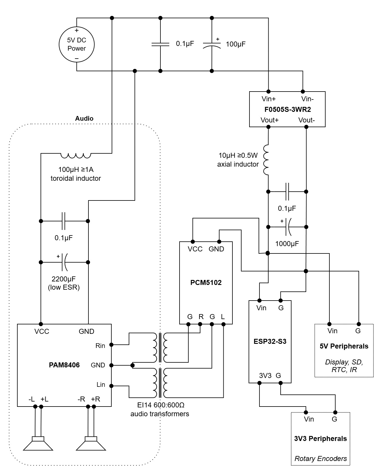
A simplified approach that keeps the F0505S-3WR2 isolation core but uses commodity parts for the filtering. This costs much less than the full Kle7rx "no compromises" build, while still providing clean isolated power to the digital side and an LC-filtered rail for the amplifier.
You may use any I2S decoder and amplifier you like for this build.
- Budget Isolation Schematic (made with draw.io)
Parts List
| Part | Qty | Purpose | Notes |
|---|---|---|---|
| F0505S-3WR2 | 1 | Isolated 5V→5V DC-DC (3W, ~20pF isolation); traps ESP32 noise on digital side | Alt: B0505S-3WR2 (budget, ~50-100pF isolation so try to avoid); same 3W/600mA |
| 100μF 10V+ electrolytic | 1 | Input smoothing for F0505S-3WR2; cleans USB charger noise | Standard electrolytic is fine |
| 10μH axial inductor (0.5W) | 1 | Inrush limiter on F0505S-3WR2 output; protects converter from 1000μF load | See Below Note |
| 100μH toroidal inductor (≥2A) | 1 | LC filter inductor for audio rail; replaces PLY17 | PAM8406 draws ~1.3A peak; search "100μH toroidal inductor 3A" |
| 2200μF 10V+ electrolytic (Low ESR) | 1 | Audio rail filter capacitor | Green "high frequency low ESR" type |
| 1000μF 10V+ electrolytic | 1 | Digital rail reservoir; handles WiFi/SD current spikes | 470μF at a minimum (but bigger is OK too) |
| 0.1μF ceramic (MLCC) | 3 | High-frequency decoupling: audio rail, F0505S input, F0505S output | X7R dielectric, marked "104" |
| EI14 600:600Ω audio transformer | 1 | Galvanic isolation on audio signal lines; breaks ground loops | Any 600:600Ω or 1:1 audio transformer |
| 5V USB power supply ≥2A | 1 | Power supply |
Note about Inrush Limiter: The output of the F0505S-3WR2 is 600mA but the 0.5W rating of a single axial inductor may actually only be 500mA. Problems will manifest as such:
- After 10 min of streaming + display on, touch the inductor. Warm = fine. Too hot to hold = overloaded.
- Startup failure: F0505S-3WR2 won't start or cycles on/off so the inductor is saturated, cap looks like a short.
- Brownouts: ESP32 resets under load - inductor's DCR climbed from overheating, voltage sagged too low.
A few solutions to these problems may be possible:
- 1 10μH 1A toroidal inductor (best, but more expensive)
- 2x 20μH axial inductors in parallel = 10μH / 1A
- 2x 10μH axial inductors in parallel = 5μH / 1A
What's cut vs the full Kle7rx build: No PLY17 chokes, no XRR6H ferrite beads, no LD06AJSA LED driver, no Mean Well PSU. PAM8406 stereo module replaces two LTK5128 mono amps. The F0505S-3WR2 isolation is preserved. It's the foundation that makes the approach work.