ehRadio Hardware Choices
There are many considerations to make when building a radio. Here are listed all of the supported hardware, some with more detail than others.
When in doubt, also consult the myoptions Generator which also contains tips about the hardware.
ESP Board
It is strongly recommended to use an ESP32-S3 board with at least 2MB of PSRAM and 8MB of flash.
It may be possible to use a board with 4MB of flash but will require special partitioning.
This code may still run on an ESP32 but without PSRAM will have serious issues that may be unfixable.
It is also possible to build with an ESP32-C3 but since that is not a dual-core CPU, it would be prudent to avoid larger and/or SPI displays.
External Antenna
Depending on your wi-fi and purpose, you may choose a board which has the option of an external antenna. Don't forget to set the jumper correctly.
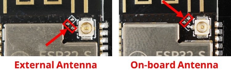
Picture from and more info here.
Important Notes (Power & Wires)
Although some modules can be powered by 3V3, use the 5V pin or direct USB power wherever possible to avoid overloading the ESP's weak 3V3 power regulator. Most modules have onboard regulators anyway.
It is recommended to use a minimum of 470µF 10V capacitor somewhere in your circuit across the 5V and GND (attach negative to GND).
It helps to stablize the system during boot and smooth out the sudden power draw during operations like initializing the decoder, screen, wi-fi, etc.
The capacitor should be as near as possible to the ESP's 5V and G pins, so it's easiest to just solder the capacitor directly to the dev board.
If that's a problem, it's not catastrophic to put elsewhere on the 5V rail. The SD Card Reader and display's 5V pins may be used.
You may size up either number, but µF is the only number that matters. To be extra safe, use a 1000 µF capacitor.
There is no benefit to using a higher volt rating like 16V or 25V or 250V. So, use what's convenient.
This capacitor can help mitigate power-supply problems but if you do encounter issues, you may find that using a better supply (preferably one that provides 2A or more) will solve many types of problems that can occur due to a weak power-supply.
An additional note here about wires. Although you may experience some success with thin wires, AWG24-22 is the "sweet spot" which you can generally use for all wires, provided the length does not exceed 30-50cm.
If you really wish to use different gauges of wire, signal wires should be thinner. AWG 28-30 is ideal for signal wires and will function at extreme lengths. Power lines should be thicker AWG20-22 but the longer they are, the more voltage can drop (but too thick also adds resistance).
Breadboards may make prototyping easy but take note of wire gauges. duPont jumper wires are typically AWG28-26 and AWG28 is not suitable for the voltage current needed in ESP32 projects. Be sure that your power wires at least are AWG26 or better.
Display
Building with a display is not strictly necessary.
Too many displays are supported to show pictures of them all here.
TFT / IPS Color Displays
SPI color TFT displays all look pretty good (IPS versions will always look better even if they don't photograph well).
| Display | Default Resolution | Other Resolutions Supported | Note |
|---|---|---|---|
| GC9A01A | 240x240 round | No | |
| GC9106 | 160x80 | No | |
| ILI9225 | 220x176 | Yes | |
| ILI9341 | 320x240 | No | |
| ILI9488 | 480x320 | Yes | uses a 24-bit bus so can be slow to update (choose the ST7796 if you want a display that updates faster) |
| ILI9486 | 480x320 | Yes | not fully tested - see notes inside the library regarding gamma correction |
| ST7735 | 160x128 | * see below * | works well, cheap |
| ST7789 | 320x240 | Yes | |
| ST7796 | 480x320 | Yes |
If the display is listed as supporting other resolutions, then the following resolutions are available: 480x320, 320x240, 284x76, 240x240, 220x176, 160x128, 160x80, and 128x128.
Non-default width or height must be specified in myoptions.h.
The ST7735 has several subtypes in the Adafruit driver, as specified by DTYPE, which also sets the resolution.
| ST7735 Subtype | Resolution | Note |
|---|---|---|
| BLACKTAB | 160x128 | default unless DYTPE is specified |
| GREENTAB | 160x128 | |
| REDTAB | 160x128 | |
| 144GREENTAB | 128x128 | |
| MINI160x80 | 160x80 |
If you have a 160x128 and the default BLACKTAB doesn't work, try GREENTAB and REDTAB.
OLED Monoochrome Displays
OLEDs are cheap, beautiful (in a retro way) and just as functional.
| Display | Interface | Default Resolution |
|---|---|---|
| SH1106 | SPI or I2C | 128x64 |
| SH1107 | SPI or I2C | 128x64 |
| SSD1305 | SPI or I2C | 128x64 |
| SSD1306 | SPI or I2C | 128x64 |
| SSD1322 | SPI only | 256x64 |
| SSD1327 | SPI or I2C | 128x64 |
All OLED displays support various resolutions: 256x64, 128x128, 128x64, and 128x32.
Non-default width or height must be specified in myoptions.h.
LCD Displays
Not recommended but supported anyways, thanks to inheriting ёRadio display architecture. LCD displays like the 1602, 2004, and Nokia 5110 may work but will not be as good-looking as the others.
| Display | Interface | Default Resolution |
|---|---|---|
| 1602 | Parallel or I2C | 16x2 characters |
| 2004 | Parallel or I2C | 20x4 characters |
| NOKIA5110 | SPI | 84x48 dot-matrix |
| ST7920 | SPI | 128x64 dot-matrix |
Audio Decoder
I2S / PCM Decoder
I2S/PCM decoders are cheap and easy-to-find but must be used with an amplifier.
I2S uses the CPU to decode data so it can be used with many types of streams. The data is then sent to a PCM decoder which turns the data into sound. It does put pressure on the CPU so it does have trouble running with large SPI displays.
A good I2S Decoder is the PCM5102A but be sure to set the jumpers as in this picture, including the 4 on the bottom and SCK=GND jumper on the other side.
H1L / FLT: low latency (instead of high latency)H2L / DEMP: de-emphasize control for 44.1KHz sample rate off (instead of on)H3L / XMST: soft un-mute control (instead of soft mute control)H4L / FMT: Audio format I2S (instead of Left justified)
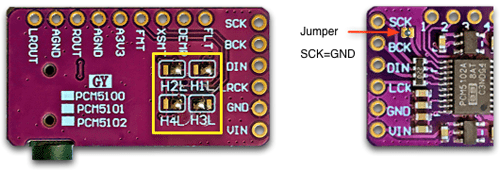
Picture and info from here.
The UDA1334 should work and there are likely others.
You will need an amplifer when building with a DAC like these. Read more below.
The ES8311 is a mono I2S decoder/amp included on some dev + display boards like the es3c28p. It's not terrible.
VS1053
The VS1053 is well-supported and may make for an easy first-build (with no amp).
The idea of the VS1053 is fantastic. It decodes streams directly and relieves pressure from the CPU. It has an acceptable built-in amplifier that has decent audio isolation already built-in. Whereas I2S decodes streams using the CPU, the VS1053 can decode most popular codecs directly on the board, relieving the CPU to handle other functions...
But the technology behind the VS1053 (2009) pre-dates the ESP8266 (2013) and the libraries have not received the same attention from developers as the I2S decoding routines.
There are many additional issues as well so it is probably best to reserve building using the VS1053 when using very slow displays like the ILI9488.
For the VU Meter to function, the patch MUST be enabled. Even with the patch, though, it struggles to decode FLAC streams and some other "unusual" stream types.
The so-called "Green Board" is the cheapest and easiest to find but don't assume it is a genuine VS1053. Some are sold as "VS1003/1053" which are almost certainly a VS1003. This can be verified by checking the LDO power-regulators. If the board has a 2.5V LDO instead of a 1.8V LDO, it's a VS1003. Genuine VS1053 is usually $10 minimum. Shop carefully and don't buy the cheapest one.
If you end up with a VS1003, it will still be functional for MP3 stations (but nothing else).
It cannot use the patch and there will be no audio if you use #define VS_PATCH_ENABLE true in myoptions.h.
Actually, even with genuine VS1053 boards, "no audio" problems can often be directly traced to the patch being applied and failing. So, unless you require the VU Meter, don't apply the patch and don't do any hardware fixes listed below...
Hardware Fixes
There are some known "fixes" that may be applied to the green board to ensure it functions as expected.
-
Simple, easy, with no known drawbacks, it is recommended to remove the resistor marked
R2. This resistor actually pulls downGPIO0of the VS1053B chip into MIDI mode at boot. Usually the internal pull-up resistor succeeds in pulling it up in time for the patch to be applied. Removing it leaves it floating so the internal pull-up always succeeds.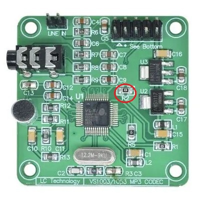
Not Recommended "Fixes"
If you are sure you have a genuine VS1053 and you're still getting problems with it, you may try the follow fixes:
-
Place 33Ω damping resistors placed right next to the ESP32 pins used for
SCK,MOSI,XCS, andXDCSbefore wiring to the VS1053 board. ESP32-S3 GPIO pins have an incredibly fast transition time (slew rate), which is around 1-2ns. Even with short wires around 10-15 cm, these sharp edges cause severe signal reflections ("ringing"). Damping resistors provide source impedance matching and damps the reflected wave, preventing data micro-glitches. Acceptable alternatives to 33Ω are in the range of 22Ω to 47Ω. No higher or lower. If a sharp edge causes ringing or cross-talk from the adjacentSCKwire on these strobe lines, the noise amplitude can falsely cross the logic threshold. As a result, the decoder might assume the communication session was interrupted right in the middle of a data frame transfer. This may manifest in the logs with excessiveslow stream, dropouts are possiblemessages as well as with audio artifacts like pops and clicks. -
Add 100Ω resistors on the
DREQandXRSTlines (middle of wire is OK) for passive filtering of pulse noise and port protection during initialization. -
Please remember that the patch is sensitive. Try disabling the patch first before assuming your VS1053 needs fixing.
For boards that identify as VS0
A board that identifies as VS0 during boot (check the serial logs) may be fixable.
There are various fixes available and it's up to you to see which one works for you.
-
Some people report that reflowing the connections on the VS1053B chip fix their issues.
-
Here is a fix that worked for Trip5 (did not attempt the reflow, ):
Attach 100KΩ resistors from the 3.3V LDO to
XCSandXDCSto pull them up. If the error persists, restore R2 with a solder bridge. It seems likely there is a parasitic drain on them that interferes with boot... You could try 500KΩ or 1MΩ or probe and remove the onboard resistors if 100KΩ isn't enough.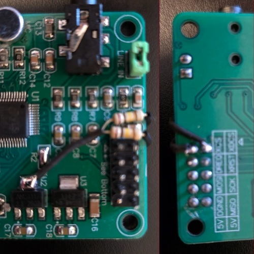
-
Other fixes may be possible, too!
For more detailed information on why these fixes are applied, the VS1053 Datasheet may prove useful reading.
Special Warning
Do not connect an amplifier directly in-circuit to the VS1053.
If you connect the VS1053's audio jack directly to an amplifier (where the audio (-) input is tied to the power supply ground), you will short the GBUF (+1.23V) directly to GND (0V). This will cause:
- Immediate overheating of the VS1053B output stage
- Severe distortion, screeching, or the chip shutting down due to protection
- Permanent damage to the VS1053B
So, either do not connect an amplifier directly to the VS1053 or be sure to add isolation using EI14 600:600Ω transformers.
Audio Amplification
When using a PCM decoder, it is absolutely essential to add an amplifier. Most VS1053 boards includes a usable but weak amplifier.
The subject of audio amplifiers is a huge topic. This is just a summary of what is known to work. You may do further research if you like.
Amplifiers
It is generally recommended to use Class-AB amplifiers because:
- no switching noise which is especially noticeable at high frequencies and with sensitive speakers
- reasonable power efficiency (but use power even when idle)
- no complicated output filters needed
- may introduce low-frequency humming
Class-D amplifiers may be used as well. They run cooler due to higher power-efficiency (due to switching) but may have a buzz or whine and the switching may introduce noise.
PAM8406
The PAM8406 is a stereo Class-D/Class-AB hybrid amplifier that offers flexibility in output mode and wide community support.
One variation has trim pots onboard, useful for balancing stereo speakers, setting a maximum volume limit, attenuate line volume to prevent clipping and distortion, and reduce gain to minimize amplification of background hiss or noise.
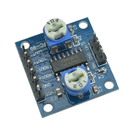
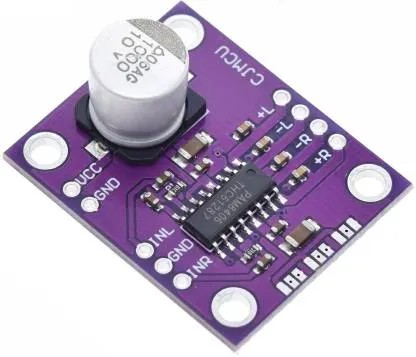
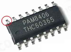
To verify the PAM8406 board's Class mode, check pin 9. If it is tied to Ground, it's in Class-AB mode. If it is tied to VCC, it is in Class-D mode.
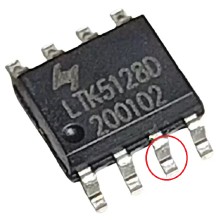
LTK5128
The LTK5128 is a mono Class-D/Class-AB hybrid amplifier and is also a good choioce.
When looking for LTK5128, get the red PCBs which are factory-configured for Class AB. The blue ones are Class D, which may or may not include jumpers to set to class AB.
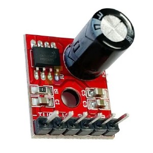
To verify the LTK5128 board's Class mode, check pin 3. If it is tied to Ground, it's in Class-AB mode. If it is tied to VCC, it is in Class-D mode.
Note Regarding Amp-Speaker Pairing
Speaker wattage is a maximum handling rating, not a minimum requirement. A 3W amp can drive 300W speakers — they'll just be quiet.
What actually matters for amp compatibility is impedance (Ω):
| Amp | Rated Impedance | Notes |
|---|---|---|
| PAM8406 | 4Ω (3W x 2) | Works at 8Ω (~1.5W per channel). Filterless Class-D, no output capacitors needed |
| PAM8403 | 4Ω (3W x 2) | Similar to PAM8406, lower power |
| PAM8610 | 4–8Ω (10W x 2) | Requires 7–15V supply (not USB). Overkill for desktop use |
| LTK5128 | 4–8Ω (3W) | Mono Class-AB. Use two for stereo |
| MAX98357A | 4–8Ω (3W) | I2S input — no DAC needed. Filterless Class-D |
For a desktop internet radio, efficient 3–10W speakers (4–8Ω) are ideal. They'll produce more volume at low power than massive high-wattage speakers whose heavy cones need serious current to move. Small bookshelf or full-range drivers work best with these amps.
Trip5's Lazy PCM/Amp Combo
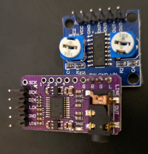
If you don't care about audio or power isolation, you can solder the PCM5102A to a PAM8406 stereo amp. The PCM5102 output pins line up pretty nicely to the PAM8406's input pins. Use the trim pots on the amplifier to attenuate/reduce input to match the speakers and minimize noise.
Audio Isolation
Audio isolation transformers EI14 600:600Ω use galvanic isolation to physically separate the input and output circuits using magnetic induction. This breaks the conductive path for DC voltage and ground loop currents, effectively stopping the 50/60Hz hum caused by potential differences between devices.
While the EI14 transformer breaks the ground loop and removes hum from the source, the amplifier itself can reintroduce noise if it generates high-frequency switching interference (common in Class-D amps) or if its power supply is noisy. For the cleanest result, pair the isolation transformer with a Class-AB amplifier or a well-filtered Class-D module.
Or even better, separate the audio and digital sides of your circuit.
Transformer Notes
The signal lines R and L from the PCM5102 audio output must be fed to the start (dot-marked) of the primary windings of the EI14 transformers; the ends of the windings go to GND. The secondary windings of the EI14 are connected to the PAM8406 similarly: the start (dot-marked) of the windings to Rin and Lin; the ends of the windings to GND.
The datasheet should identify the winding starts. They may not actually have little dots printed on the physical transformer.
You might instead encounter:
- pin numbering showing winding polarity
- a schematic in the datasheet showing the winding starts
- a "1" marking on one side of each winding
- coloured wires with a specified polarity
- a manufacturer's pinout such as 1–2 = primary, 3–4 = secondary, with pin 1 and pin 3 being the corresponding starts
If the transformer is literally just described as "EI14 600:600 Ω" with four unmarked pins and no datasheet/pinout, then you don't know the polarity from the 600:600 specification alone.
Audio/Power Noise
If you find that your amplifier is buzzing, there are a few things to blame for this.
One suspect is usually backlight control. Typically these use PWM (Pulse Width Management) to achieve dimming. That adds interference. The easy fix is to disable dimming and tie the BL pin to 3V3.
Full Audio/Power Isolation
You can read some (untested) schematics to achieve Audio/Power Isolation.
Controls
ehRadio can be built with various control methods, including rotary encoders, buttons, an IR receiver, touchscreen, WebUI, Home Assistant, MQTT, Telnet, and HTTP.
The most basic physical control is a rotary encoder. All major functions can be accomplished with just one encoder.
Buttons may also be used. Touch is swipe and tap motions only.
Information on how the controls function detailed are here.
Wake from Deep Sleep
Wake from deep sleep is only possible on RTC-capable pins. On the ESP32, these are RTC GPIOs: 0, 2, 4, 12-15, 25-27, 32-39.
ESP32-S3/C3 RTC GPIOs are: 0-21.
All inputs assigned to these pins will automatically be used for wake.
If no inputs are available on these pins, deep sleep will be disabled.
Deep sleep may be explicitly disabled with #define DEEP_SLEEP_DISABLE in myoptions.h.
Rotary Encoders
The KY-040 module is very easy to setup. It includes the correct resistors onboard.
Other rotary encoders like the EC11 may also be used but may require 10KΩ resistors to pull down CLK and DT to Ground.
Buttons
Momentary switches should not require any special resistors but may require attention in myoptions.h since they are usually pulled-up by default.
You can also use a joystick instead of connecting five buttons.

IR Receiver
IR receivers like the VS1838 are cheap and work well. You may need a pullup resistor. The KY-022 module or TSOP38238 may work as well.
SD Card Reader
An SD card reader may be added to the build. It is recommended to be wary of SD readers built onto displays. Although some may work, it is well-known that some may be lacking proper resistors or will interfere with display because it is forced onto the same SPI bus.
It is highly recommended to use an SD card reader with a power regulator and a 74VHCT125A buffer. If needing to make this type fit with a case, the excess PCB around the slot may be cut off carefully with a knife, sandpaper, or grinding tool. Wear a mask if filing or grinding! Fiberglass is bad for your lungs!
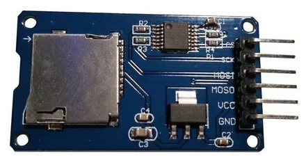
A simpler SD card reader may work but may cause random, unsolvable issues. Do not use on the same SPI bus as other devices.
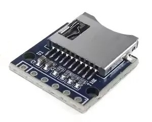
It is recommended to encode files on SD card using MP3 at a constant bit rate of 256kbps or less to avoid system stress and get maximum compatibility with the decoders. ABR and CBR encoding may work (mostly) but may also result in pops and clicks. Errors/bugs could happen if you use other codecs or too-high bitrates or other codecs.
SD Cards
SD cards on these cheap SD readers can be pretty finicky.
Certain brands are known to work better than others: Sandisks and Samsungs are recommended.
Make sure it's "Class 10" or "UHS-I U1" and formatted FAT32.
Smaller sizes (32GB and smaller) may also work better.
Windows disk format does not like formatting larger SD cards but the command line format /FS:FAT32 X: /Q will work for larger sizes.
When in doubt or experiencing problems, try a different SD card.
SD Offline Mode
The SD Offline mode should be considered as a "fallback because wi-fi is not available" mode, not a primary playback mode.
By default, all buttons and encoder switches can be used to enter this mode on boot.
If you wish to use a special pin, add something like #define SDOFFLINE_BTN 2 or #define SDOFFLINE_BTN BTN_DOWN to myoptions.h.
TS_INT cannot be used for this purpose as the touchscreen is floating at boot.
Remember that certain GPIOs may cause issues if held while powering-up (so best not to attach buttons to GPIO0 or GPIO3).
Most users will not remember the difference between "shortly after power-up" and "during power-up".
RTC
An I2C RTC module may be added to the build as well. This should keep the time when network connectivity is unavailable.
Supported RTC modules include DS3231 and DS1307.